Installation & Testing
Loading an image:
Since this POV design stores the image in program memory space, the microcontroller must be re-programmed every time you want to load a new image. The process is as follows:
- Create a 700x700 pixel, 8 bit per pixel image and save it with an 8 character filename. Image data must be saved as a headerless RAW file. For more information on this format, refer to the POVIMAGE.BAS section of the Theory page.
- Edit POVIMAGE.BAS so that it references the new image and run the program. It will save its output with a .ASM extension.
- Copy and paste the .ASM output into the POV firmware file (628h.asm). To find where the image data is located in the firmware, open 628h.asm and search for the comment that says "; Page boundary, image data starts here." ...Everything from that point up until just before the last line (which is an "end" statement), is image data.
- If you’re using a 7.2 volt battery pack, then you must edit line 149 of the firmware as follows:
From this (8.4 volt): MOVLW 0x8D
To this (7.2 volt): MOVLW 0xAE
This adjusts the internal reference voltage for the LowBattery routine. - Compile it and program the POV board through the four pin In Circuit Serial Programming (ICSP) connector. This connector does not supply power to the board while it’s being programmed, so you must supply power externally or with the battery pack.
Testing:
Test the operation of the POV board by applying power and waving a magnet in front of the hall effect sensor. You should see the LEDs illuminate. If they do not light up, turn the magnet over and try again. The faster you wave the magnet in front of the sensor, the faster the LEDs should flash. If this test fails to illuminate the LEDs, the most likely causes are a defective or damaged hall effect sensor or a bad program.
The plastic backing:
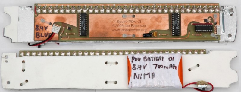
To mount these boards in the wheel, I made a protective backing out of 1/8" Sintra (often used as a rigid backing onto which printed material can be mounted), covered one side with anti-static plastic that was cut from a motherboard bag and attached it to the solder side of the circuit boards with zip ties. I’m not sure if the anti-static plastic is of any benefit, but I used it as a precaution in case a static charge builds up on the Sintra as the wheel spins. On one end of the sintra, I cut a crescent shaped notch that matched the radius of my front hub shaft. On the other end, I cut a curve to match the inside contour of the rim and drilled two holes for zip ties. All that is needed to secure a circuit board to the wheel is two zip ties at the spoke nipple end - the other end stays put because the crescent shaped notch engages around the wheel hub.
Securing the boards at the hub:
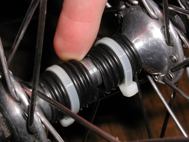
To keep the hub end of the boards in place, I used two short sections of plastic hose, slit down one side, wrapped around
the hub shaft and attached with zip ties. These act as spacers that prevent the boards from sliding laterally along the
length of the hub shaft.
Note: These boards will fit a 26" or larger wheel. Also, when using three boards, it’s easier to mount them
in a wheel with a number of spokes that’s divisible by three (IE 36 spokes).
Mounting the magnet:
To trigger the hall effect sensors, I used a stack of four magnets from an old 3.5" hard drive. The stack of magnets was placed on the inside of one of the bike forks above the region under which the hall effect sensor passed, then secured in place with a piece of tape.