Tools
- For fabricating the PC boards:
- Computer and laser printer
- Hacksaw
- Stainless steel wool
- Laser printer toner transfer papers such as Pulsar or Techniks Press-n-Peel Blue(TM)
- Heat laminator such as the GBC H200
- Ferric chloride
- Liquid tin solution (optional)
- Long tupperware containers
- Plastic funnel
- Dremel with drill press attachment
- 0.04" carbide drill bit
- For soldering components:
- Soldering station
- Solder sucker
- Multimeter
- Bench power supply
- Needlenose pliers
- Diagonal cutters
- For programming the microcontrollers:
- PIC programmer with In Circuit Serial Programming (ICSP) capability
- Computer
- For mounting the boards in a bike wheel:
- Utility knife
- Ruler
- Fine tipped marker
- Safety gear:
- Safety glasses
- Nitrile rubber gloves
- Leather gloves
- Earplugs
- Dust mask
Parts list
| Qty. | DigiKey part No. | Description |
| 3 | PIC16F628A-I/P-ND | PIC 16F628A microcontroller |
| 3 | A9418-ND | 18 pin IC sockets |
| 200 | 160-1620-ND | Red oval LEDs |
| 6 | 3M5466-ND | 24 pin IC sockets |
| 6 | 497-3874-ND | STP16C596 LED sink driver |
| 9 | 10KQBK-ND | 10K 0.25 watt resistors |
| 6 | 1.0KQBK-ND | 1.0K 0.25 watt resistors |
| 3 | P5174-ND | 1uf 16 volt electrolytic capacitors |
| 3 | 399-2171-ND | 0.1uf ceramic capacitors |
| 6 | DN6851-A-ND | Hall effect sensors (only 3 are needed) |
| 3 | LM2931AZ-5.0-ND | 5 volt low dropout regulators |
| 1 | 182-1018-ND | Double sided 0.032" 1/2oz copper clad board |
| 1 | PC300C-60-ND | 0.04" carbide drill bit |
| 1 | 182-1003-ND | Pulsar toner transfer sheets |
| 1 | 182-1021-ND | Pulsar green TRF film |
- Only 3 hall effect sensors are required but they are easily damaged, so I’ve specified 6 in the table.
- The carbide drill bit is very hard, but also very brittle. Make sure you don’t apply any lateral loads.
- If you can’t find the STP16C596 LED driver in your region, then one of these may work as a substitute: Allegro A6276EA, Maxim MAX6969ANG (check out www.farnell.com)
- Note: I’ve tested the MAX6971ANG and although it looks like it should work, it does not.
- If you can’t find the DN6851-A hall effect sensor, the DN6849SE may work as a substitute.
- I’ve specified 0.032" copper clad board which is half the thickness of the regular stuff. This is so that it will fit through the "Toner Applicator" from Pulsar. If you don’t plan to use this device, then you can use thicker board.
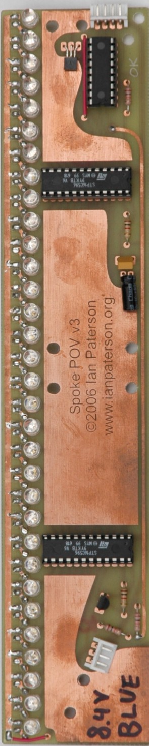
Printed circuit board
In the past, I’ve used the photo etch method to make circuit boards, but the process was difficult, costly, messy and time consuming. This time, I decided to try the toner transfer method. This is a process whereby you use a laser printer to print your PC board layout on a special sheet of paper, then you transfer the toner from the paper to the copper clad board with heat and pressure. After the toner has been "re-fused", the paper is removed by soaking the board in water. Finally, a sealant is applied over top of the transfered toner to prevent pinholes when the board is etched.The three boards for the Spoke POV were done in this way. I used toner transfer sheets from Pulsar, and applied them to the copper clad boards with a common household iron (no steam). Although I was successful in making three functional boards, I found the process finicky and one board needed a lot of touch up work to make it serviceable. Most of my troubles came from trying to transfer the PC layout from the paper to the copper clad board - It was hard to get it to stick evenly without smearing or shifting. Later on, I switched to a modified GBC H200 heat laminator and had much better results.
Note: More recently, I’ve had the greatest success with the Press-N-Peel Blue product from www.techniks.com. The sheets can be easily applied with a modified GBC Heatseal H200 laminator and they can be removed just by peeling - no soaking necessary.
Soldering the LEDs:
The LEDs are controlled in pairs, one for each side of the board, thus allowing the POV image to be viewed from either side of the bicycle. The LED pairs are connected in series by way of small jumper wires that serve the same purpose as a PC board via. The biggest challenge in soldering these jumpers is that the heat from your soldering iron will travel along the wire and melt the connection on the other side of the board. I found it helpful to use those "Helping Hands" soldering aids with alligator clips to hold the wire in place. If you are able to make PC boards with vias, then these jumpers are not necessary.Soldering the Hall Effect sensors:
For me, the most troublesome part of this project is soldering the Hall Effect sensors without damaging them. Because they are sensitive to both mechanical and thermal stress, you must use great care when attaching them to the circuit board. When bending the leads, you must hold the sensor lead with needlenose pliers between the plastic case and the point at which the lead is being bent. This is to prevent mechanical stress at the point where the lead enters the sensor’s case. When soldering, you must also use needlenose pliers as a heat sink to prevent damage from excessive heat. Once the sensors have been successfully soldered onto the board, there is little risk of further damage.
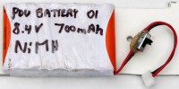
Batteries:
This circuit is capable of simultaneously driving all of its LEDs at 20mA each, which means each board could draw as much as 1.5A. For this reason, you should use batteries that are capable of delivering high current such as NiMH, Li-ion or Li-polymer. The battery voltage needs to be high enough to allow the regulator to provide 5V for the microcontroller and also just high enough to allow the LED drivers to deliver up to 20mA through each LED pair. Try using a 7.2V battery pack for LEDs with a low forward voltage (such as red) and 8.4V for other colours (such as white and blue). Be sure not to use a battery voltage that’s more than about 2 volts higher than 2x the forward LED voltage, otherwise the LED drivers may be damaged. Note: Depending on the battery voltage you choose, you may have to edit line 149 of the firmware. See step 4 of the Loading an image section for more info.
You can use one battery pack to drive all three POV boards, but this would require some kind of wiring harness
to connect to all the boards. A much tidier solution is to have a dedicated battery pack mounted to the back
of each board. Custom battery manufacturers that specialize in handheld radio, laptop and RC model batteries
should be able to fabricate custom NiMH packs from AAA cells that meet your exact requirements. For a set of
white POV boards, I had a local battery shop make three 8.4V packs with 700mAH NiMH AAA cells spot-welded into
a series pack and shrink wrapped. The finished product was very professional looking and could easily be mounted
to the back of the POV boards.
If you want to try using standard alkaline cells which cannot deliver such high current, you can reduce the LED
drive current by increasing the value of the resistors attached to pin 23 of the LED drivers. (See table at right)
Please note that I have not tested the performance and reliability of the POV boards when used with alkaline cells.
The cells can be mounted in standard spring-loaded battery holders between the circuit boards, affixed to intersecting
pairs of spokes with zip ties. Due to the large number of mechanical connections present when using spring-loaded
battery holders, you may experience reliability problems due to vibration, dust, moisture, etc.