NEW IMPROVED VERSION NOW ONLINE:
Overview
This circuit is based on a PIC16F628A microcontroller which sends serial data through a series of four 74HC595 eight bit shift registers that in turn drive 32 LED pairs. 2N3904 transistors are used to switch the LEDs on and off so that all LEDs can be simultaneously driven at 20mA each, indefinitely, without damaging the shift registers. One kilobyte of image data is stored in the program memory area of the microcontroller and is read by way of a lookup table. The firmware uses three interrupt routines to do its job:- An interrupt to provide the time interval between radial raster lines
- One to increment a counter for timing the wheel rotation interval
- And finally, one to reset all counters and update the raster interval value every time the hall effect sensor is triggered
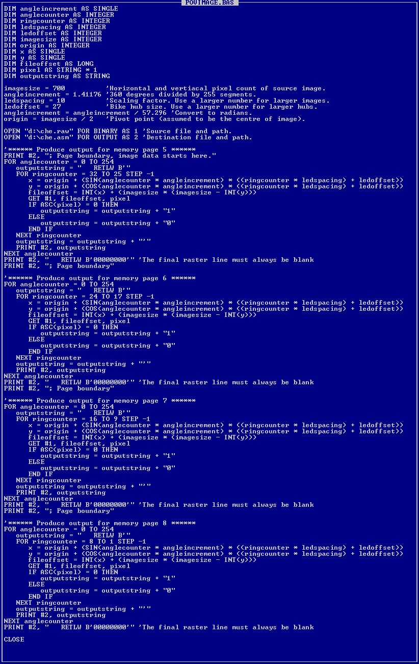
Rather than compute timing values for the radial raster line interval, I decided to use a lookup table in the firmware and just compute the values for that table with a Qbasic program. Also, in order to generate POV image data, I wrote a Qbasic program that reads a 700x700 pixel raster file and outputs radial raster data to a text file that can be copied and pasted directly into the assembly code of the microcontroller.
Features
When I set out to design this device, these were some of the features I had in mind:- Support for In Circuit Serial Programming (ICSP)
- 32 LEDs on each side of each circuit board (64 LEDs per board, 192 LEDs total)
- The ability to display a 1 kilobyte image (32 LEDs x 256 radial "raster lines")
- Discrete transistors driving the LEDs (so all LEDs can be run at 100% duty indefinitely)
- Voltage regulation for the ICs only (so a 1 amp voltage regulator can be used)
Flowcharts
The following flowcharts illustrate the logic in Spoke POV's various firmware routines. Both program and image data exist within the program memory space of the PIC 16F628A microcontroller. This means that there is no mechanism for uploading image data at runtime. The chip must be reprogrammed if you want to display a different image.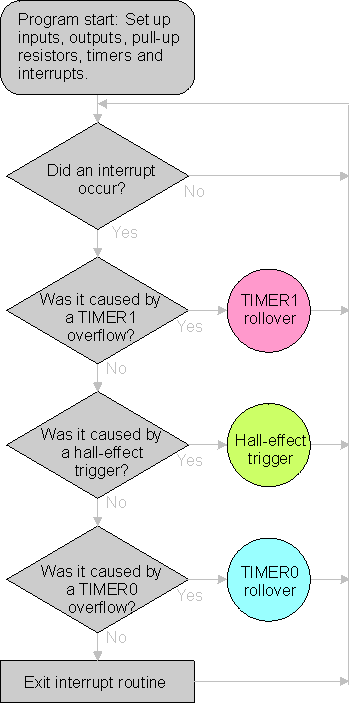
Main program flowchart:
This is the main program loop that decides what interrupt routine to run. After the initial startup instructions, the first thing it does is loop endlessly until an interrupt happens. The rest of the code runs entirely within interrupt servicing routines. (The pink, green and blue circles)TIMER1 rollover flowchart:
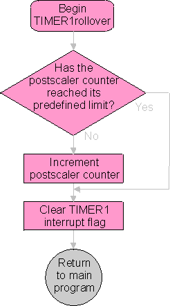
TIMER1 is used to measure the time elapsed during one complete wheel revolution. The only problem was that even when the TIMER1 prescaler was set to its maximum value, it still wasn't long enough to measure one revolution at low speed (walking speed). Of course a persistent image would never be visible at such a speed, but I wanted to strive for a fairly wide operating range. In order to overcome the TIMER1 limitation, I decided to increment a counter so that TIMER1 could do two complete cycles, which takes about one second. (One wheel revolution per second is a reasonably slow riding pace.) After two complete cycles of TIMER1, this "postscaler" counter stops incrementing.
Hall effect trigger flowchart:
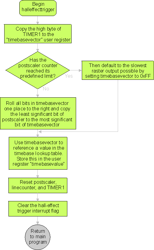
The halleffecttrigger routine is where we determine the timebase for the radial "raster lines".
The least significant bit of the TIMER1 "postscaler" is combined with the seven most significant
bits from the high byte of TIMER1. The resulting number is used to reference a timebase value in a lookup
table. After that, TIMER1, the TIMER1 postscaler and the raster line counter are reset and then we return
to the main routine.
Since we can only know the duration of one wheel revolution after it has happened,
the timing of the LED raster output is always lagging behind slightly. If the rider is moving at a constant
speed, this is not a problem, however if the rider changes speed, the image will become slightly
distorted. In practice, this distortion isn’t really a big deal.
TIMER0 rollover flowchart:
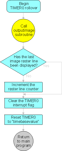
The TIMER0 rollover routine is responsible for displaying radial raster lines at a rate dictated by the timebase value acquired from the hall effect trigger routine. Whenever TIMER0 overflows, this routine calls the outputimage routine to display one radial raster line of the image. A counter is used to keep track of which raster line is to be displayed next. Once the last raster line has been displayed, the counter stops incrementing. Finally, before returning to the main program, this routine resets TIMER0 to the timebase value.
Outputimage flowchart:

This routine fetches image data from a lookup table. To avoid the problems associated with trying to access a lookup table that crosses memory page boundaries, I've chosen an image size that occupies exactly four consecutive memory pages and then interleaved the image data across them, with each raster line composed of one byte from each page. That way, one simply has to load PCLATH with the appropriate page number prior to fetching each byte. After fetching each byte of image data, this routine calls the writebyte routine which sends the data serially out to the shift registers.
Writebyte flowchart:
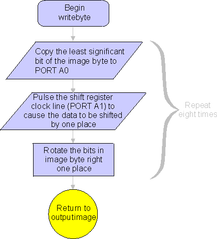
The writebyte routine sends serial image data to the shift registers. It does this by copying the least significant bit of an image byte, rotating the bits in the image byte one place to the right, then repeating the process for all remaining bits. After a bit is copied, the shift register clock line must be pulsed so that the data in the shift register is "shifted" over by one place, making room for the next bit.
Shift registers
My initial thought was to find a PIC microcontroller that had at least 32 output lines (like the 16F877) so that I could drive each LED pair with a seperate output line, but then I learned about shift registers. These devices can be used to convert serial data into parallel data, so that only three output lines are needed regardless of the number of LEDs in the array. Of course, because the data is output serially, there is a practical upper limit to the number of LEDs that can be used because of the time required to display a raster line.The device chosen for this project was the 74HC595 which holds eight bits and allows multiple devices to be cascaded together. It also has a seperate storage register that allows one set of data to be displayed while the next set is being loaded. In this circuit, four key lines are used: serial data (SER), serial data clock (SRCLK), storage register clock (RCLK) and serial output (QH’). Each pulse of the serial data clock line causes the data to be "shifted" over by one place and each pulse of the storage register clock line causes the parallel outputs to reflect the contents of the shift register. Note that in the illustration below, the storage register is represented as a bank of switches, but it is in fact a bank of D-type flip-flops that can store eight bits while another eight are being loaded in the shift register.

The Qbasic programs
In addition to the microcontroller firmware, two Qbasic programs are required for setting the timing values and converting image data so they can be incorporated in the firmware.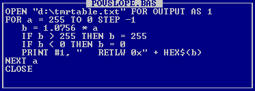
POVSLOPE.BAS:
This program simply creates the timebase lookup table. I probably could have done the necessary calculations in firmware but I decided to use a lookup table instead. Besides, I think it may use fewer instruction cycles this way.The table produced by this program is linear, so the only parameters one needs to be concerned with are slope and offset. Curently, I don't think the slope and offset values are quite as accurate as they could be. In the future, I plan to build a test rig that uses a 555 timer to generate a series of pulses to simulate the triggering of the hall effect sensor. I then plan to use a dual trace oscilloscope to read the trigger pulses and an LED output that has been programmed to fire only on the last raster line of the image. This way I can test the circuit timing by comparing the two oscilloscope traces. (the last raster line should always fire just before the next hall effect trigger)
POVIMAGE.BAS:
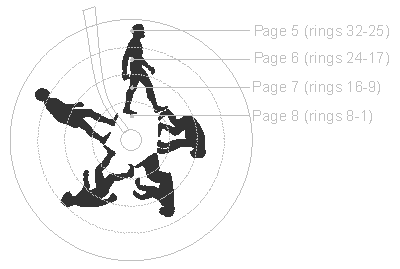
Because of the limitations of Qbasic and the fact that I didn’t want to bother figuring out how to read TIFF files, I’ve made it read headerless RAW files. The images must be 700x700 pixels, greyscale, 8 bits per pixel, with the pixels being either pure black (0x00) or pure white (0xff). Such a file can be created with Photoshop.
To keep this device from lighting up when the bike is stationary, the last raster line is always set to zero (off). Because the firmware stops incrementing the raster line counter when it reaches the last line in the image, having all LEDs off in that line will cause them to ramain that way until the next hall effect trigger.
Possible improvements
I’d love to hear from anyone who has ideas or suggestions on how this circuit could be improved. My email address is on the Contact page.Here are some improvements that I’m considering:
- Get rid of the timing lookup table and perform calculations within firmware instead
- Improve timing accuracy (see text under POVSLOPE.BAS)
- The 16F628A has a built in USART. Perhaps there’s some advantage to using it for serial output to the shift registers?
- Add a power switch?
- Use a microcontroller with more memory so it can hold more than one image
- Ambitious: The ability to upload image data on the fly via Bluetooth wireless technology