Navigation path: Home > Projects
Overview
This page is my best attempt at describing how I built an interface to control a 200 disc CD changer and the challenges I encountered along the way. I got rid of the hardware for this project several years ago and I’ve had to piece together the information about it from old notes, photos and my own memory so please be aware there might be some holes in the info provided here. Because CD changer technology largely is obsolete now, I can’t imagine anyone wanting to replicate my project, however some of the principles could be applied to interfacing with other consumer electronics products so perhaps this project will be of interest to some people.
In the late 1990s, most people’s music collections primarily consisted of CDs. Portable mp3 players were just beginning to appear on the market and they could only hold a couple of hours of music at most, so if you wanted to make your own extended playlists, a multi-disc CD changer was really the only sensible option.
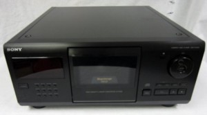
Sony CDP-CX205 200 disc changer
In 1999, I had a Sony CDP-CX205 200 disc CD changer loaded with my entire music collection which consisted of about 120 discs. The changer was one of Sony’s more basic models at the time, which allowed you to program up to 32 "steps", each one of which could be a single track or an entire disc. It could only hold one of these programs at a time and there was no provision for loading and saving programs. To overcome my changer’s limitations, I decided to build an interface that would allow me to control the changer with a computer and therefore be able to load and save an unlimited number of playlists.
Circuit Details
Here are the options I was considering for interfacing with the changer:
- Build a circuit that could send infrared signals to the changer’s infrared remote receiver.
- Interface directly to the changer’s Control-S port at the back of the unit
- Interface directly to the changer’s infrared receiver hardware. (closely related to Control-S)
- Build a circuit that interfaces with the keypad on the remote control or the buttons on the unit’s front panel.
Back then, the only programming language I could use comfortably was Qbasic and I felt it would be too difficult to figure out how to simulate the changer’s IR protocol and then control an IR transmitter with that language. If I were to try interfacing directly with the changer’s IR receiver hardware or the Control-S input, I wouldn’t have to worry about IR modulators but I would still be faced with the same challenges regarding the serial protocol.


In the end, I chose to try the keypad interface method. I had some experience with CMOS analog multiplexers and felt I could use them to simulate the pressing of buttons and could control them easily through the PC’s parallel port. So, with the "button pressing" method in mind, I decided to try to tap into the keypad matrix of the changer’s infrared remote. The majority of infrared remote controls use an x and y matrix of lines to read button presses as illustrated in Figure 1. An example of how analog multiplexers can be used on the x and y axes of the matrix can be seen in Figure 2. Note that it’s not necessary to remove the original keys in order to do this.
For my circuit, I used one multiplexer on the x axis, another on the y, then I tied the common line from one multiplexer to the common line of the other. This worked, but for the purpose of my project, it had some problems. First of all, the infrared link to the changer wasn’t 100% reliable, especially when a large number of button presses were sent in rapid succession. Secondly, there was no way for the controller to know what state the changer was in because the communication was unidirectional. So, I soon scrapped the idea of interfacing with the remote’s keypad and instead, I decided to interface directly with the front panel of the changer.


After poking around inside the changer for a while, I realized that it didn’t use the same matrix keypad method as the remote. Instead, it used resistor ladders with a momentary button to ground on each segment of the ladder (see Figure 3). In total, the changer used 3 ladders like this, so you could control any key press by interfacing with just 4 wires (3 + ground). After reverse-engineering the front panel to see what the resistor ladder values were, I modified my circuit accordingly and found I could control the changer much more reliably than before. My interface didn’t need to make use of all the buttons however, so rather than duplicating the resistor ladders in the changer, I decided to pick out only those buttons that I needed and calculate the total resistance for each of those buttons by adding up all the resistors above it in the ladder. Essentially, my interface would use a dedicated resistor for each multiplexer input and all the resistors would be in parallel instead of series. This meant I could interface with only those buttons that I needed and I could add or remove buttons without affecting the others (see Figure 4).
The changer used two additional wires for controlling the jog shuttle. Internally, the jog shuttle drove two staggered rotary switches, one for each of the jog lines. As the shuttle wheel was turned, the rotary switches would produce four different combinations: low-high, low-low, high-low and high-high in that order. If the jog shuttle motion was reversed, then the switching order would be reversed and that’s how the changer knew which direction the shuttle wheel was being rotated. When connecting the jog shuttle wires to my interface, I needed to make sure that they were not connected to the same multiplexer because each multiplexer could only switch to one line at a time, yet there would be times when both jog shuttle lines would need to be switched on simultaneously (see Figure 5).

Once I had the resistor values figured out, I decided which buttons needed to be controlled and connected the appropriate resistor values to arbitrary inputs on my two multiplexers. The table in Figure 6 shows the various key lines on the changer, the various resistor values used and the byte that must be sent to the PC’s parallel port for any given button.


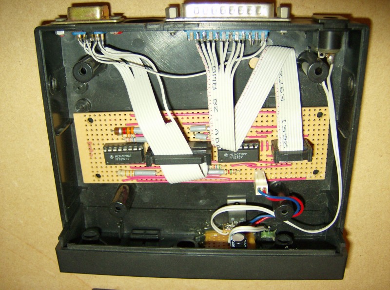
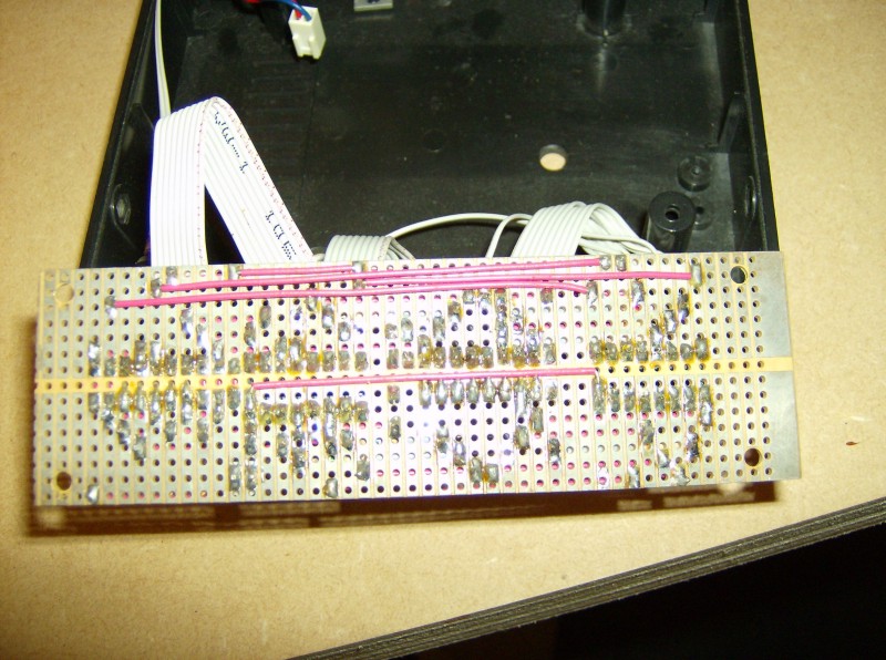
Since the circuit is simple with very few components, I decided to build it on
a piece of Veroboard (stripboard). Here are some photos:
The Qbasic Program
After I had the hardware interface problems sorted out, I needed a program to simulate keypresses by outputting the necessary bytes to the parallel port. I’m somewhat embarrassed to say that I decided to write the program in Qbasic because it was the only language I was really comfortable with at the time. The program used a very crude text-based interface that ran under DOS. In the end, it met my needs satisfactorily, so I didn’t put any effort into making it user-friendly or pretty after I got it working. During the writing of the program, I ran into three challenges that are worth noting:
The first problem I enountered had to do with finding a sequence of keypresses that would bring the changer into a known state. The reason for this was because when using the changer’s front panel, you had to select a particular disc with the jog shuttle and the number of jog pulses required was always relative to the current disc number. In other words, if you wanted to access disc #50, you would need a different number of jog pulses if your current disc was 20 than if it was 35. In the end, I was able to find a complicated sequence of key presses that always reset the current disc number to 1. The magic sequence turned out to be: make sure no buttons are being pressed, then press STOP, then PROGRAM, then hold the CLEAR button for a second or so, then press BLOCK 2, then BLOCK 1, then finally PROGRAM again. This sequence can be seen in the SonyInitialize subroutine.
The second challenge I encountered was knowing when the current track had finished playing so I could instruct the changer to queue up the next track. To solve that, I ended up running a wire from the SELECT line on the parallel port to the LED on the changer’s play button, which would only illuminate when a track was playing.
The final challenge had to do with the LPRINT command. I initially used LPRINT
for sending bytes to the parallel port, but it turned out that it would not send 13D, 111D or 191D. Instead, it sent a 10D. (There may
have been other characters that LPRINT would not send as well.) To fix the problem, I switched to the
OUT <address>, <byte> command instead, but it took me a couple of days of head scratching before I
figured out the problem.
The computer hardware requirements for running the jukebox control program are minimal. I ran mine on a very early DOS-based "tablet" style computer with a 386SX-16 processor and a monochrome 640x480 LCD display. Unfortunately, I don’t have any photos of this machine. It had a somewhat ruggedized construction and was encased in rubber, so I think it may have been used by couriers or perhaps for inventory control in a warehouse. Here’s the Qbasic program that ran on it:
It’s probably worth noting that timing is critical for it to function correctly and it’s entirely dependent on the speed of the computer. I had to use trial and error to come up with the correct timing values for my little 386 PC and then I hard-coded them into the program under the "delay assignments" section.
Final thoughts
At the time, I really got great satisfaction from this project when everything was finally working properly, even though it became obsolete not too long afterwards. If I had to build this interface over again, I’m sure I would do things differently. I would probably use a microcontroller to simulate Control-S signals and I’d control the microcontroller via the PC’s serial interface or possibly USB. That would mean the CD changer would not have to be modified and furthermore, it would allow the controller to be used with other Sony products with very little modification.